Mecholic | Addicted To Mechanical Engineering -->
Showing posts with label IC Engines. Show all posts

How To Reset Camshaft Position Sensor?

CPS


Resetting the camshaft position sensor can resolve many engine issues related to improper camshaft timing. Follow the steps to properly disconnect and reconnect the sensor and allow the vehicle’s computer to re-learn the sensor position.

Camshaft Position Sensor: Function and Purpose in Automotive Engines

Camshaft Position Sensor


What is a Camshaft Position Sensor?

In an automobile engine, a camshaft position sensor plays a critical role. A camshaft position sensor is an electronic device that monitors the position of the camshaft in an internal combustion engine. It is located either on the camshaft itself or on the engine block near the camshaft. Depending on the make, model, and design of the engine, the exact location of the camshaft position sensor may differ. Typically, an engine will have one camshaft position sensor on each camshaft.

Can You Drive with A Bad Crankshaft Position Sensor

Can You Drive with A Bad Crankshaft Position Sensor.png


Driving for an extended period with a bad crankshaft position sensor is not recommended. This is because the sensor plays a critical role in the engine management system, providing important information about the position and speed of the crankshaft to the engine control module (ECM). If the sensor is not functioning properly, the ECM may not be able to accurately control fuel injection, ignition timing, and other engine functions.

How The Crankshaft Position Sensor Is Tested?

Crankshaft Position Sensor Test


🔗Common Issues with Crankshaft Position Sensor


In case of suspicion that the crankshaft position sensor may cause the problem or if a related trouble code is detected, it is essential to visually inspect the sensor for any visible damage, such as cracks, loose or corroded connector pins, or other issues. It is also essential to maintain the proper gap between the sensor tip and the reluctor ring (or disc).

Common Issues with Crankshaft Position Sensor


Like any other component of an engine, the crankshaft position sensor can fail or malfunction over time. Failure of the crankshaft position sensor can occur due to burning out, wearing out, or simply reaching the end of its lifespan after extensive use. Another common cause of failure is extreme heat exposure vibration-induced wire fracture, and corrosion on harness connector pins. Many modern crankshaft sensors are designed as sealed units that can withstand exposure to water or other fluids. When the sensor fails, it stops transmitting the signal containing critical data for the ignition and other system components.

Types Of Crankshaft Position Sensors How They Work?

Types of Crankshaft Position


🔗Crankshaft Position Sensor: What Is It, Why Is It Important?


Various kinds of crankshaft position sensors are available, each with its own set of characteristics. These include inductive sensors, Hall Effect sensors, magnetoresistive sensors, and optical sensors. Among these, inductive sensors are the simplest in construction, which are usually passive devices.


Crankshaft Position Sensor: What Is It, Why Is It Important?

Crankshaft Position Sensor: What Is It, And Why Is It Important?


The effective functioning of automotive control systems relies not only on pressure sensing but also on the precise measurement of the position of shafts, valves, and levers. In automotive electronics, measuring the angular position or velocity of shafts is common. The crankshaft position sensor (CPS) is essential to modern engines. It plays a crucial role in providing vital information to the engine control module (ECM), which controls ignition timing, fuel injection sequencing and is responsible for regulating various engine functions. In this article, we will discuss a crankshaft position sensor, its importance, its functions, and its advantages.

What Is Preignition - Causes and Disadvantages of Preignition


What is preignition?

Preignition is a phenomenon in the IC engine in which homogeneous fuel charge burned before the normal ignition starts (or in the absence of spark). The preignition is initiated by the overheated projecting parts such as spark plug, exhaust valve head, carbonaceous deposits and hot spot in the combustion chamber. The autoignition (or knocking) may overheat spark plug, valve head and it remains so hot that it may ignite the fuel charge in compression stroke of the next cycle.

Difference Between Knocking and Detonation? Theories of Knocking

Detonation


What is the difference between knocking and detonation?

“Knocking” and “detonation” are the interchangeable terms refers to the phenomenon of uncontrolled combustion in the IC engine. “Knock” is the sharp metal pinging sound produced in the engine due to uneven combustion. There are generally two theories for knocking. 1) auto-ignition theory and 2) detonation theory. These theories led many people to use the term detonation for knocking. In general, detonation is the cause and knocking is the after effect.

What Are the Various Factors Influencing Flame Propagation?

Flame speed


Abnormality in SI engine like detonation is depends on the rate of pressure rise in the combustion chamber. Since the rate of pressure rise directly related to the rate of flame propagation, it is very important to study about the factors affecting flame propagation. Important factors that influence the flame propagation is listed below.


Flame Propagation and Flame Speed Across the Combustion Chamber and Factors Affecting Flame Propagation

Flame propagation in SI engine

Flame propagation and flame speed

Flame propagation is defined as the progress (spread) of the flame inside the engine cylinder (combustible environment) outward from the point at which the combustion started. Flame generally propagates spherically. The rate of radial propagation of flame is known as flame speed. It is typically measured in m/s. It gives an idea about how rapidly fame propagates from a reference point. The flame speed determines the ability of a fuel to undergo controlled combustion without detonation.

Difference between Battery Ignition System and Magneto Ignition System in SI Engine


Battery Ignition System
Magneto Ignition System
Current required for spark or primary is circuit is obtained from a battery.
It produces the electricity required for spark plug or primary with its own electric generator.

This type of ignition system Battery is a necessary component.
Magneto ignition system does not need a battery.

The problem of discharged battery.
Since it does not require a battery there is no problem of discharged battery.

It is heavy and requires more space than a Magneto type.
 It occupies less space when compared to battery type.

Quality of spark does not depend on the engine speed.
The quality of spark depends on the engine speed.

Good quality spark is obtained at low speed.
At low speed or at starting the quality of spark is poor because the generator produces less energy than required.

At high speed, the spark intensity reduces, and hence the efficiency of system decreases.
As speed increases the spark intensity also increases. It improves the efficiency of the system.

Since this system contains battery it requires high maintenance.
Less maintenance is required when compared to battery type.

It finds application in SI engines of cars and light commercial vehicle.
They are mainly used in racing cars and two-wheelers.


Magneto Ignition System Construction, Working, Applications, Advantages and Limitations

schematic magneto ignition system

Working of magneto ignition system

Working Magneto ignition similar to the battery ignition system except in the source of energy for operation. The magneto ignition system has its own generator (magneto) to supply necessary energy for the system. There are three types of magnet ignition system

  • Rotating magnet
  • Rotating armature
  • Polar inductor type

Battery Ignition System/ Coil Ignition System Working, Advantages and Disadvantages

Battery ignition system

Read: Battery ignition system construction and essential components

The main components of a battery ignition system are battery, ignition switch, ballast resistor, ignition coil, contact breaker, capacitor, distributor and spark plug. The source of high voltage/energy for the spark plug is the ignition coil, hence it is also called ignition coil system. Following figure shows a diagram of a conventional battery ignition system.

Battery Ignition System/ Coil Ignition System Construction and Essential Components

Car_ignition_system battery

🔗Difference between battery ignition system and magneto ignition system

Battery ignition is the most common type of ignition system. Since ignition coil plays a major role in this system, it is also called Coil Ignition System. They are used in cars, light trucks and in some two-wheelers. The above figure shows a battery ignition system for four-cylinder petrol engine.

Introduction Ignition Systems of SI Engine, What Are the Requirements of an Ignition System?

SI engine ignition

SI engine ignition systems

In a CI engine, air-fuel mixture gets ignited at a high compression ratio. But in an SI engine, it is not the case. The SI engine works the pressure ratio lower than that of CI engine. The SI engine requires an external source of an energy to initiate the combustion process. Engine ignition systems are the tools that used to ignite SI engine.

Solex Carburetor Working, Advantages Of Solex Carburetor


Solex carburetor construction and working principle

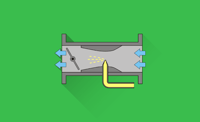
Solex carburetor is famous for its performance, reliability, and ease of starting. The figure shows a diagram of a downdraught solex carburetor. This type of carburetor has distinct fuel circuit for starting, idling, acceleration, low speed operations, etc. Provisions on solex carburetor ensure the supply of richer mixture at starting, and weaker mixture during cruising of the engine.

Multiple Venturi Carburetor Construction and Working, Advantages of Multiple Venturi Carburetors


How multiple venturi carburetor works?

When one or more secondary venturi concentrically enclosed inside the main venturi of carburetor, then it is called multiple venturi carburetor. The secondary venturies are known as boost venturi. The boost venturi located at the upstream of the main venturi. The boost venturi positioned in such a way that the discharge end is located at the throat of main venturi and the pressure at the exit of boost venturi is equal to the throat pressure of main venturi. In this arrangement, only a fraction of air flow thought the boost venturi. The fuel nozzle is located at the throat of boost venturi.

Difference between Constant Choke Carburetor and Constant Vacuum Carburetor

carburetor constant vacuum constant choke

🔗What is carburation?
🔗Design and working principle of simple carburetor

What is a constant choke carburetor?

Constant choke carburetor is the type of carburetor in which the air and fuel flow area is always kept constant. In constant choke carburetor, the air-fuel ratio is changed due to varying pressure difference or depression as per the demand. This type of carburetor should have a compensating device to avoid air-fuel mixture enrichment with the increase in speed. Example: Solex carburetor and Zenith carburetor.

🔗Multiple venturi carburetor construction, working, advantages

Differences between Petrol and Liquid Petroleum Gas (LPG)

petrol vs lpg

Comparison between petrol and liquid petroleum gas

🔗Advantages and disadvantages of liquid petroleum gas (LPG)

Petrol
Liquid Petroleum Gas (LPG)
Petrol is in the liquid phase at ambient condition.
LPG is in gases sate at ambient condition, it is liquefied at high pressure.
Petrol has odour
LPG is odourless. Powerful odorant like ethanethiol is added to LPG to detect the fuel leakage.
Combustion is not clean as in the LPG
Clean combustion.
High emission when compared to LPG
Low emission
Ignition temperature is lower than LPG
High ignition temperature
Noisier and vibration when compared to LPG engine