Mecholic | Addicted To Mechanical Engineering -->
Showing posts with label Theory of Machines. Show all posts

Grashof's Law - Formula and Significance

Four Bar Chain


Understanding Grashof's Law in Mechanics


Grashof's Law is a fundamental concept in mechanism design and kinematics that describes the relationship between the length of the crank and connecting rod in slider-crank mechanisms. Grashof's Law plays an important role in the theoretical analysis and practical design of mechanisms across diverse engineering fields, including machines, motors, robotics, and more. Let’s look deeper at what exactly Grashof's Law states and how it informs the design of linkage assemblies.

What Is Chain Drive? Advantages and Disadvantages of chain drive over Belt and Rope Drive

chain drive animated

Introduction to chain drive

The belt drive and rope drive used in power transmission suffers the some extent of slipping. Then chain drive come into compete with other type by avoiding slipping. The chain drive is a way of mechanical power transmission. It consist of endless series of chain link known as roller chain which meshed with toothed sprocket gear. This type of power transmission mainly used in motor cycle.

Essential Properties and Qualities of Bearing Metals

bearing

The selection of the type of bearing metals depends upon on the conditions under which the bearing used such as temperature, bearing pressure, type of lubrication, rubbing speed etc. However, they must possess some general qualities. The desired characteristics of bearing materials are listed below.

Governor Controlling Force and Controlling Force Diagram

Governor Controlling Force and Controlling Force Diagram

Controlling force

When governor running each ball of the governor subjected an inward pull. Consider a governor running at a steady speed, then the inward force acting on the rotating governor ball is known as controlling force. Controlling force of governor is equal and opposite to the centrifugal reaction.
Controlling Force, Fc = mω2r

In porter governor controlling force is provided by the weight of sleeve and balls. In spring controlled governor (eg: Hartnell governor) controlling force provided by spring and weights.

What Is Meant By Effort And Power Of A Governor?

effort power governor

Read: What Is A Governor?

Governor effort and governor power are the tools that can be used to compare different type of governor.

Effort of Governor

Effort of governor is defined as the mean force exerted at the sleeve of governor for a given percentage of change in speed of spindle or lift of sleeve. When governor running at constant speed, the force exerted on the sleeve is zero. When the governor speed changes the spindle moves up or down to new equilibrium position. There will be a force that prevents this movement of sleeve. The resistance is equal to Effort of governor. This resistance varies from maximum to minimum as the sleeve moves to the new equilibrium position.

Pickering Governor Construction, Working and Equations

Pickering Governor diagram

Construction and working of Pickering Governor

Pickering governor is very simple in construction and it is used for small machines. The sleeve movement in Pickering governor is very small when compared to the other centrifugal governor. It controls the speed by dissipating excess kinetic energy.

Wilson-Hartnell Governor Construction and working

willson-hartnell governor


Construction and working of Wilson-Hartnell Governor

A Wilson-Hartnell Governor is shown in above figure. In this type of governor has a primary/ main spring and an auxiliary spring. The main spring arranged symmetrically on either side of the axis and it connects two flying balls on the vertical arms of bell crank lever. The horizontal arms of bell crank lever carry rollers which press against the sleeve of governor. An adjustable auxiliary spring is attached to sleeve mechanism of governor through a pivoted lever.  The Purpose of this auxiliary spring is that to adjust the equilibrium speed for a given radius of rotation. The auxiliary spring tends to keep sleeve down.

Hartung Governor Construction, Working and Equations

hartung governor image
 
Read: What is the purpose engine governor?

Construction and working of Hartung Governor

Hartung governor is a type of spring controlled governor. The various parts of a Hartung governor are indicated in above figure. The bell cranks are pivoted at O, O’ to the frame. The horizontal bell crank livers are attached to the roller fits into the grooves of the sleeve. Sleeve is free to move up and down along the central axis of Hartung governor by two keys. The vertical arm of bell crank lever is fitted with spring balls which compress against the frame of the governor. The spring opposes the centrifugal force acting on the spring balls.

Equation of Energy Loss by Friction Clutch During Engagement

friction transmission clutch diagram
 
Read: What is a Clutch? - Types of Clutches

Consider a plate or disc clutch
Let
IA = mass moment inertia of rotors attached to shaft A
IB = mass moment inertia of rotors attached to shaft B
ωA = Angular speed of shat A before engagement
ωB = Angular speed of shat B before engagement
ω = Common angular speed of shat A and Shaft B after engagement

According to the principle of conservation of momentum, Total momentum before clutch engage is equal to the total momentum of the clutch after clutch disc engagement.

IA ωA + IB ωB = (IA + IB

Common angular speed after engagement of clutch pressure plate
ω=  (I_A ω_A+I_B ω_B)/(I_A+I_B ) common angular speed

Total Kinetic energy before friction clutch engagement
E_1=1/2 I_A 〖ω_A〗^2+  1/2 I_B 〖ω_B〗^2 E_1=1/2 〖(I〗_A 〖ω_A〗^2+I_B 〖ω_B〗^2) Energy equation before engagement

Kinetic energy after clutch engagement
E_2=1/2 〖(I〗_A+I_b)ω^2 energy equation after engagement

Put the value of ω into above equation,
E_2=1/2 〖(I〗_A+I_b)〖((I_A ω_A+I_B ω_B)/(I_A+I_B ))〗^2 =  〖〖(I〗_A ω_A+I_B ω_B)〗^2/(2(I_A+I_B)) energy equation after engagement of clutch

Now the loss of energy during clutch engagement, E= E1-E2
E=  1/2 〖(I〗_A 〖ω_A〗^2+I_B 〖ω_B〗^2)-〖〖(I〗_A ω_A+I_B ω_B)〗^2/(2(I_A+I_B)) E=  (I_A I_B 〖(ω_A-ω_B)〗^2)/(2(I_A+I_B))   energy loss by friction during clutch engagement


Apply Different condition for above equation
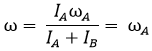
Condition I - The rotor attached and hence the shaft B at rest ωB = 0
Put these condition in equation (a), and equation (b) we get
Common angular speed after the clutch engagement,
ω=  (I_A ω_A)/(I_A+I_B ) coomon angular speed

Loss of kinetic energy
E=  (I_A I_B 〖ω_A〗^2)/(2(I_A+I_B)) energy loss

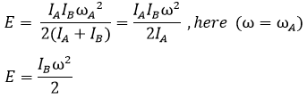
Condition II - If rotor B at rest (ωB = 0) and IB is very small when compared to IA
Common angular speed after the clutch engagement,
ω=  (I_A ω_A)/(I_A+I_B )= ω_A common angular speed

Kinetic energy loss,
E=  (I_A I_B 〖ω_A〗^2)/(2(I_A+I_B))=(I_A I_B ω^2)/(2I_A )  ,here  (ω=ω_A) E=(I_B ω^2)/2 kinetic energy loss

What Is The Difference Between Statics, Dynamics, Kinematics, And Kinetics?

mechanics linetics statics dynamics kinematics

Statics: It is the branch of mechanics which deals with the analysis of loads and their effect on a system when its acceleration is zero or it is static equilibrium with the environment (relative motion is zero). The system may be in stationary or it is center of mass moves at constant velocity. However, term statics usually represent the analysis of loads on the stationary rigid body. The load on the system are force, torque or momentum.