Hartung Governor Construction, Working and Equations


Read: What is the purpose engine governor?
🔗 Comparison between Centrifugal and Inertia Governor
🔗 What is the difference between Flywheel and Governor?
The working of Hartung Governor is similar to the Hartnell governor. When the spindle speed increase, spring balls tends to fly away from the spindle. The outward movement of the fly ball causes the upward movement of the sleeve at the other end of bell crank lever. Upward movement of sleeve results in lower fuel supply and thereby the decrease the speed of engine.
When the speed of governor spindle decreases the ball radius decreases. That causes the upward movement of governor spindle and then increase in fuel supply.
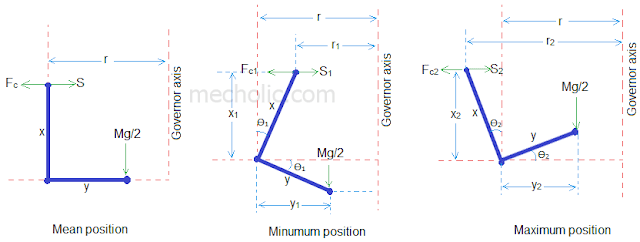
Figure show a free-body diagram of Hartung governor in mean, minimum and maximum position.
Here Fc = Centrifugal force
S = Spring force
k = Stiffness of spring
M = Mass of sleeve
m = Mass of spring ball
r = Radius
ω = Angular speed of spring ball
x and y = Length of the vertical and horizontal arm of Hartung governor.
Consider the mean position
Take the moments about O, we get
Fc x = S x + Mgy/2
Here
Fc= mω2r
S = k * change in spring length
Construction and working of Hartung Governor
Hartung governor is a type of spring controlled governor. The various parts of a Hartung governor are indicated in above figure. The bell cranks are pivoted at O, O’ to the frame. The horizontal bell crank livers are attached to the roller fits into the grooves of the sleeve. Sleeve is free to move up and down along the central axis of Hartung governor by two keys. The vertical arm of bell crank lever is fitted with spring balls which compress against the frame of the governor. The spring opposes the centrifugal force acting on the spring balls.🔗 Comparison between Centrifugal and Inertia Governor
🔗 What is the difference between Flywheel and Governor?
The working of Hartung Governor is similar to the Hartnell governor. When the spindle speed increase, spring balls tends to fly away from the spindle. The outward movement of the fly ball causes the upward movement of the sleeve at the other end of bell crank lever. Upward movement of sleeve results in lower fuel supply and thereby the decrease the speed of engine.
When the speed of governor spindle decreases the ball radius decreases. That causes the upward movement of governor spindle and then increase in fuel supply.
Useful equations

Figure show a free-body diagram of Hartung governor in mean, minimum and maximum position.
Here Fc = Centrifugal force
S = Spring force
k = Stiffness of spring
M = Mass of sleeve
m = Mass of spring ball
r = Radius
ω = Angular speed of spring ball
x and y = Length of the vertical and horizontal arm of Hartung governor.
Consider the mean position
Take the moments about O, we get
Fc x = S x + Mgy/2
Here
Fc= mω2r
S = k * change in spring length