Essential Parts And Working Principle Of A Centrifugal Pump
What is Centrifugal Pump? Working principle of centrifugal pump
A centrifugal pump is a rotodynamic pump that creates fluid flow by using a rotating impeller to impart energy. It operates as a reverse of an inward radial flow reaction turbine. The Francis turbine and centrifugal pump share a similar design; however, the fluid flow in the latter is opposite.
The centrifugal pump operates on the principle of forced vortex flow, means that as you rotate a certain amount of liquid by an external torque, the pressure rises in that liquid. Which give enough centrifugal force to lift liquids from a lower level to a higher level.
At any point in the rotating liquid, the increase in pressure head is proportional to the square of the liquid's tangential velocity there.
i.e.,
As a result, the rise in the pressure head will be greater at the outlet of the impeller where the radius is greater, and liquid will be discharged there with a high-pressure head. The high-pressure head of this liquid can be used to lift it to a high level.
Component or construction of a centrifugal pump
The following are the essential parts of a centrifugal pump:
1. Impeller (or Rotor)
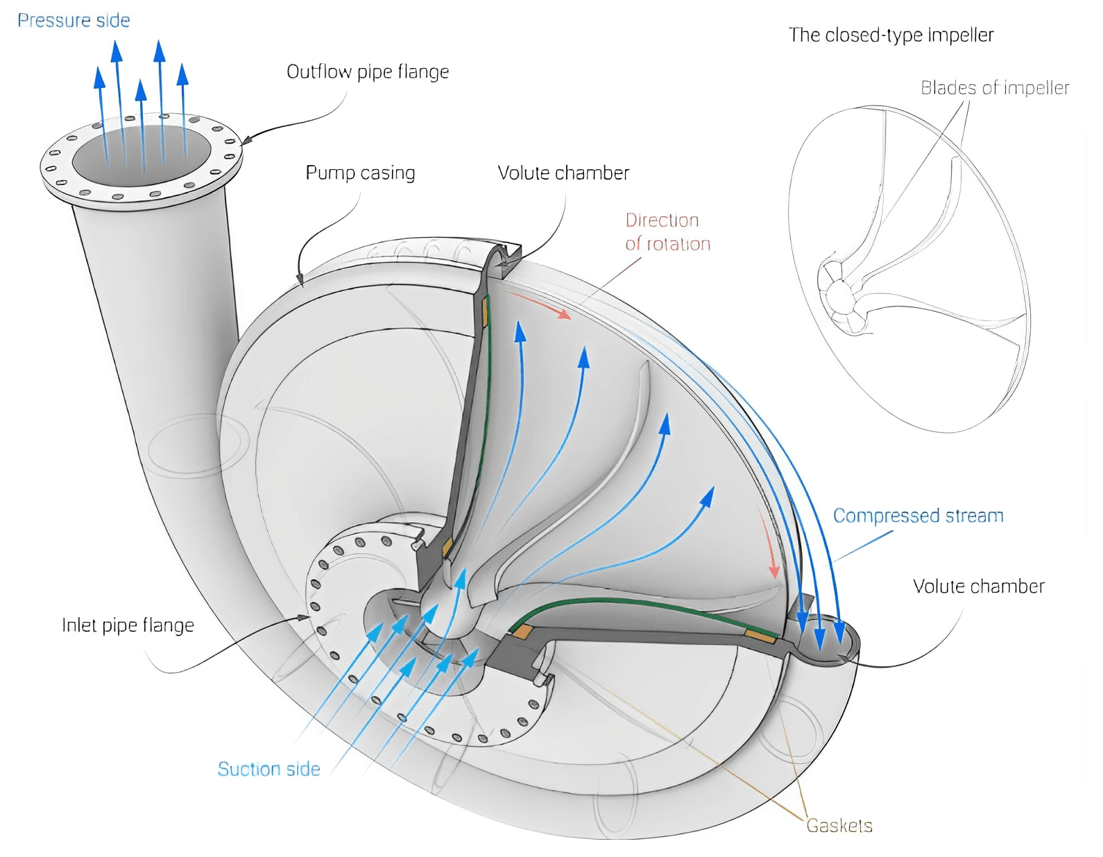
The impeller is the rotating part of a centrifugal pump. The impeller is made of a solid disc with a series of backward curved blades (vanes) protruding vertically from its face. The impeller is mounted on a shaft which is typically coupled to an electric motor or another power source. The fluid that is drawn into the blade passageways at the impeller inlet (eye of the pump) is propelled radially outwards and accelerated as the impeller rotates. The fluid's static pressure is increased in this way. The liquid exiting the impeller is then led through the pump casing under high pressure.
🔗Types of impellers in a centrifugal pump and their application
🔗Applications advantages and disadvantages of centrifugal pump
2. Casing
A centrifugal pump's casing is similar to the casing of a reaction turbine. The casing is an airtight chamber that encloses the pump impeller. The centrifugal pump casing is designed to convert the kinetic energy of liquid discharged at the outlet of the impeller into pressure energy before it leaves the casing and enters a delivery pipe.
The casing has a provision for suction and discharge arrangement, supports for bearings and facilitates housing for the rotor assembly. It also has provisions to fix stuffing box and house packing materials to prevent leakage.
The casing serves two main purposes:
(i) To direct liquid to and from the impeller, and
(ii) To partially convert kinetic energy into pressure energy.
🔗What are the Purpose of casing in centrifugal pump?
🔗Types of casing used in centrifugal pump with their advantages and limitations
3. Suction pipe
A suction pipe is a pipe whose one end is connected to the pump's inlet (the center or eye of an impeller), and its other end dips into a sump of working fluid. A non-return valve, known as a foot valve, is fitted at the lower end of the suction pipe. It opens only in the upward direction, prevents the draining of liquid when the pump is not working and helps to priming. A strainer at the lower end of the suction pipe prevents solid particles and debris from entering the pump from the working fluid.
4. Delivery pipe
One end of the delivery pipe is connected to the pump's outlet, and the other delivers the working fluid at the required height. A regulating valve is installed on the delivery pipe to control the liquid flow.
5. Prime Mover
An electric motor is typically coupled with the pump shaft to provide the necessary energy to the impeller. When the diesel generator is set as the prime mover, the power is usually transmitted to the pump shaft through a belting system.
🔗Classification of centrifugal pump
🔗Centrifugal pump vs Positive displacement pump


